![]()
球状マイクロフォン
Surround Microphone System by Bruck
with KFM 360 and DSP-4 KFM 360
- compact, highly effective arrangement
- extensive capability for post-processing in digital domain (many important parameters can be adjusted after the recording has been made)
- digital and analog inputs and outputs
- analog-style controls
- user preference settings can be stored and recalled
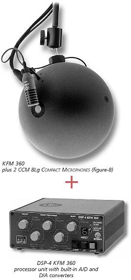
The complete surround microphone system consists of:
- KFM 360 sphere microphone with SGC-KFM suspension for two figure-8s
- two figure-8 microphones (CCM 8L) and
- the DSP-4 KFM 360 processor.
These components are also available separately.
The central unit in this system is the KFM 360 sphere microphone. It uses two pressure transducers and can also be used for stereophonic recording. Its recording angle* is ca. 120°, thus permitting closer miking than the pure stereo microphone KFM 6 (90°). The necessary high-frequency compensation for the pressure transducers is built into the processor unit.
Surround capability is achieved through the use of two figure-8 microphones, which can be attached next to the pressure transducers by an adjustable, detachable clamp system with bayonet-style connectors (SGC-KFM). The main axes of these two microphones should be aimed precisely forward.
The DSP-4 KFM 360 processor derives the four “corner” channels (L, R, LS, RS) from the microphone signals. A center channel signal is obtained from the two front signals. An additional output channel is provided which carries only the frequencies below 70 Hz. To avoid perceiving the presence of the rear loudspeakers one can lower the level of their signals, delay them and/or set an upper limit on their frequency response.
The front stereo image width is adjustable, and the directional patterns of the front-facing and rear-facing pairs of “virtual microphones” (see “Operating principle” below) can be chosen independently of one another.
The processor unit offers both analog and digital inputs for the microphone signals. In addition to providing gain, it offers high-frequency compensation for the pressure transducers as well as low-frequency compensation for the figure-8s.
As with M/S recording, matrixing can be performed during post-production. All matrixing in the DSP-4 is performed in the digital domain.The front and rear channels result from the sum (front) and difference (rear) of the omnidirectional and figure-8 microphones on each side respectively (see illustration). The four resulting “virtual microphones” which this process creates will seem to be aimed forward and backward, as the figure-8s are.
At higher frequencies, however, they will seem to be aimed further outward. Their directional pattern can be varied anywhere from omnidirectional to cardioid to figure-8; the pattern of the two rear-facing virtual microphones can be different from that of the two forward-facing ones. Altering the directional patterns alters the sound as well, in ways that are not possible with ordinary equalizers. This permits a flexible means of adapting to a recording situation ? to the acoustic conditions in the recording space ? and this can even be done during post-production if the unprocessed microphone signals are recorded.
The signals from the four “virtual microphones“ comprise a type of surround reproduction which is valid in its own terms but lacks the center channel and low-frequency channel of the standard 5.1 approach, so these additional facilities are provided by the digital signal processor.The complete KFM surround set consists of:
- KFM 360 sphere microphone
- 1× KG ball-and-socket joint for mounting on a stand
- 2× CCM 8 L Compact Microphone (as a matched pair); included: K 5 LU adapter cable (Lemo/ XLR-3M), SGC stand clamp with swivel and a polished wood case
- 2× SGC-KFM mounting clamp for CCM 8
- DSP-4 KFM processor with mains cable and wood case
- 3× AK SU/2U adapter cable (XLR-5F to 2× XLR-3M) for connecting the processor’s analog outputs
- 1× KS 5U stereo cable for connecting the KFM 360
- (5 m long; advantage: only one cable is necessary for two channels)
- 1× KLY 250/5 SU, Y-cable, 5 m long, for connecting the two CCM 8 to the processor
Available separately:
for the KS 5 U and KLY 250/5 SU cables:
extension cables (e.g. KS 10 U, 10 m; KS 20 U, 20 m)for the KFM 360:
KKFM wood case and HKFM suspension deviceWhen a KFM 360 is ordered separately, it comes with
- 1× KG, 2× SGC-KFM
- 1× AK SU/2U (XLR-5F / 2× XLR-3M)
Manual (PDF with 0.8 MB)
Technical specifications* Recording angle: the range within which the sound sources should be placed, as “seen“ by the microphone